MenuClose
Internal Radial Clearance
Internal Radial Clearance of ball and roller bearings is an important parameter in obtaining proper machine operation, optimal bearing life, and a reasonable operating temperature. With radial bearings of the deep groove ball, cylindrical roller, and spherical roller types, the term Internal Radial Clearance - IRC - is commonly employed. This is the total clearance inside a bearing in the radial direction. Its numerical value can be calculated by subtracting from the diameter of the outer race roller path or ball groove I.D. two times the rolling element diameter and the O.D. size of the inner race roller path or ball groove. On small cylindrical roller and ball bearings, it can be easily measured with a dial indicator gage by laying the bearing on one side, fixing one race, and pushing the other race one direction and pulling back 180º. IRC is the total movement; however, this method does not lend itself to large, heavy industrial bearings. For two and four row tapered roller bearings of all sizes, it is very difficult to measure clearance in a radial direction and is generally not done. Instead, with tapered roller bearings, the internal clearance is defined by an axial clearance or Bench End Play – BEP. Small two row tapered roller bearings can be checked by hand, but this method will not work with large industrial bearings. The BEP value has to be calculated from drop measurements after loading and flipping the components.
Measuring the IRC of spherical roller bearings is often an absolute necessity when mounting the tapered bore versions. They can be mounted either directly on a shaft that has an accurately ground tapered journal or an adapter sleeve that slides onto the shaft with a tapered O.D. Installation involves forcing the tapered inner race of these bearings up the taper, usually with a jam nut. Larger bearings may require a hydraulic nut to drive it up. It is then secured with a regular nut that is torqued. The recommended procedure for doing this involves measuring the IRC of the spherical roller bearing with feeler gage before mounting. As it is driven up the taper in increments, the IRC is continually checked with the feeler gauge. For each bearing, there is a recommended reduction in IRC that signals the bearing has been properly driven up and the desired tightness obtained. When the desired reduction is obtained by subtracting the final IRC from the initial IRC, the bearing is driven up no more. Consistency of the “feel” results in a fairly accurate measurement of the difference between bench and mounted clearances.
Standard Internal Radial Clearance values for deep groove ball, cylindrical roller, and spherical roller bearings are found in Tables XV through XXII. Please note that there are different standards for metric deep groove ball bearings and inch ball bearings, as well as ISO cylindrical roller bearings and domestic cylindrical roller bearings. Also, the IRC values differ for straight bore bearings versus bearings with a tapered bore. There are no standards for tapered roller bearings. “Clearance” values for these bearings are expressed axially as “lateral” or “Bench End Play” (BEP) and are designed and specified for each application.
A word of caution, regarding IRC for those selecting ISO deep groove ball, cylindrical roller, and spherical roller bearings, is the “Normal” IRC shown in the tables for these bearings is not sufficient for these bearings if the bearing employs a “heavy” shaft fit. A heavy fit in most cases requires a “C3” IRC as a bearing with a “Normal” IRC could be too tight. A light to medium fit with a relatively high operating speed that generates heat also requires a “C3” IRC. If both a heavy fit is used along with a high speed, a “C4” IRC is typically required. Very few bearings with “Normal” IRC are used or stocked, with “C3” bearings being the most popular. For complicated applications, we recommend that users of our bearings contact our sales department for specific fitting and clearance recommendations.
Bearings We Offer
American Roller Bearing primarily makes heavy duty bearings that are used in various industries in the US and around the world. Not only must our industrial class bearings provide long in-service life from a rolling fatigue criterion, but they must also hold together structurally from impacts, overloads, and occasional high-speed excursions. The design of every heavy-duty bearing has been optimized to this end, including our large bore bearings.
- Ball Bearings
- Cylindrical Roller Bearings
- Tapered Roller Bearings
- Spherical Roller Bearings
- Thrust Bearings
- Custom Bearings
Bearing Fitting Practice
Proper fitting of bearing races to shafts and housings is necessary for satisfactory bearing performance and longevity of these machine components. The proper fits require very accurate machining or grinding of shaft journal O.D.s and housing bores. Allowed tolerances are only slightly larger than those of the mating bearing components. Surface finishes and deviation from the form are also an important concern. Proper shaft O.D.s and housing bores provide two important functions:
- Prevent race rotation relative to the shaft or housing and resultant fretting and galling.
- Provide proper support to the relatively thin bearing races. Without proper fits, the bearings may have to be removed from service sooner and the shaft and housing surfaces may need re-conditioned before replacement bearings can be installed.
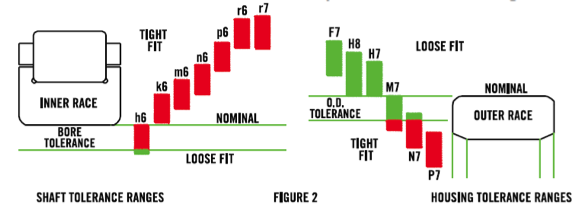
The fits and tolerances tabulated herein are reproduced from ABMA Standards (American Bearing Manufacturers Association) and are in accordance with those of ANSI (American National Standards Institute) and ISO (International Organization for Standardization). Fits are shown as a combination of a letter and a single digit number such as m6 and H7. A lower case letter indicates an outside diameter, such as a shaft journal O.D., while a capital letter indicates an I.D., such as a housing bore. The various letters indicate the location of the resultant fit tolerance zone with respect to the nominal diameter, while the number indicates the relative magnitude of the tolerance. All fits are based on the Normal tolerances for bearing bores and O.D.s. As both bearing bore size and O.D. increase, their Normal tolerances increase as does the absolute tolerances for the shaft O.D.s and housing bores. Figure 2 is a graphic representation of the relationship to the various fits with the bearing bore and O.D. tolerances. Shaft fits represented above the bearing bore indicate an interference fit. Housing fits above the bearing O.D. represent a clearance fit, while those below the bearing O.D. represent an interference fit. Some letter classes of fits allow both a clearance and a slight interference with the bearing component.
The first step in selecting the proper shaft and housing fits for a bearing is to determine whether the load rotates with respect to the Inner Race or Outer Race. The second step is determining the relative loading on the bearing. This applies to radial bearings that are subjected to primarily a radial load. Thrust bearings and bearings capable of handling combined radial and thrust loads when subjected to only pure thrust load are fitted differently.
Relative loading is defined by the C/P ratio, which is the bearing’s Dynamic Capacity (C) divided by the equivalent radial load (P). In most cases, a bearing mounted on a shaft that turns has a rotating load with respect to the Inner Race and stationary load with respect to the Outer Race. If the shaft is fixed or stationary and the Outer Race is in a wheel, gear, or some other component that turns, the load rotates with respect to the Outer Race and is stationary on the Inner Race. In a few rare situations, the load can rotate with respect to both races, and both races need to be tightly fitted. In such cases, a separable bearing is needed so that both components can be fitted individually. Suitable separable bearings are certain configurations of Cylindrical Roller Bearings and Tapered Roller Bearings.
The recommended fits shown in Tables XXIII to XXVI in the fitting practices section are reproduced from ISO/ABMA specifications. One exception is the fit for thin inner race cylindrical roller bearings that are heavily loaded, i.e. C/P less than 3. A common practice for sizing shaft journals that mount the two or more bearings with the same bore size is to use the recommended shaft O.D. for the most heavily loaded bearing in all locations. This eliminates the chance of a worker putting the wrong size on journals with the same nominal diameter.
It should also be noted that recommended fits only apply to solid steel shafts. This allows a sufficient “stretch” of the Inner Race to develop the proper “fit pressure” to resist the turning of the race on the shaft. In the rare instance that a bearing is fitted to a shaft with a modulus of elasticity less than that of steel, a tighter fit is also required. If the shaft is steel but has a hole through it, a tighter fit is also required. For either or both of these two situations, if they occur, please contact American’s Sales Department for specific shaft fit recommendation.
Mounting Inner and Outer Races
The usual method of mounting large industrial inner races on shafts is to heat the separable inner race or whole bearing in an oven or in oil. A temperature of 93ºC (200ºF) is usually sufficient to expand the bearing’s bore greater than the shaft O.D., but 121ºC (250ºF) gives a little more margin for error. When mounting, it is advisable to have a piece of pipe matching the inner race I.D. and O.D. and some soft steel drifts handy in case the inner race gets stuck on the shaft. Usually, this happens if the race gets cocked slightly. A quick tap on the right place on the inner race will usually straighten it out so it can be further pushed against a shaft shoulder before it cools and becomes fixed.
Outer races with the most commonly used H7 fit can be tapped into place with soft steel drifts as the fit is “line-to-line” to loose. Bearing races should never be struck directly with any kind of hammer, especially if they have guiding flanges and cages. A drift allows accurate placement of the impact at the solid part of a bearing race. When a slight interference fit is needed, the recommended procedure is to heat the housing to expand the bore for the bearing’s O.D. Another method often used is to chill the outer race, usually in liquid alcohol with dry ice. Installation is fairly easy, but the disadvantage is the cold bearings are subject to condensation and corrosion if preventative steps are not taken. Bearing components should not be cooled lower than -46˚C (-50˚F) or metallurgical transformation can occur causing dimensional change when the component comes back to room temperature.
Reduction of Internal Clearance
When a bearing’s inner race is mounted on a shaft with an interference fit, some expansion of the inner race O.D. (roller path or ball groove) occurs. This has the effect of reducing the manufactured or “bench” internal clearance of the bearing. This is a very important consideration when designing a machine. If the effective reduction of Internal Radial Clearance (IRC) is not properly calculated, there may not be enough bench IRC provided by the bearing to result in some operating or running clearance. Some internal clearance is necessary to prevent excessive heat generation by the bearing, which would result in a thermal runaway situation. This occurs when initial operation generates heat that results in a higher bearing temperature that causes a “negative” internal clearance, which generates more heat increasing bearing temperature, and so on. If the bearing becomes too hot for the lubrication, failure will rapidly occur.
For help in selecting bearing fits and bench Internal Radial Clearance, please contact American’s sales department.
Internal Clearance Tables
- Table XIX Radial Clearance for Domestic Cylindrical Roller Bearings
- Table XV Radial Clearance for ISO Metric Deep Groove Ball Bearings
- Table XVI Radial Clearance for Inch Series Deep Groove Ball Bearings
- Table XVII Radial Clearance for ISO Cylindrical Roller Bearings Straight Bore
- Table XVIII Radial Clearance for ISO Cylindrical Roller Bearings Tapered Bore
- Table XX Radial Clearance for Inch Series Cylindrical Roller Bearings
- Table XXI Radial Clearance for Spherical Roller Bearings Straight Bore
- Table XXII Radial Clearance for Spherical Roller Bearings Tapered Bore
Tolerance Tables
- Table IV Inner Race Bore and Width Tolerances
- Table IX Journal Cylindrical Roller Bearings Inner Races Inch
- Table V ISO Outer Race OD Tolerances
- Table VI ISO Tapered Bore Tolerances
- Table VII Inner Race Bore Tolerance Tapered Roller Bearings Inch Design
- Table VIII Outer Race OD Tolerance Tapered Roller Bearings Inch Design
- Table X Journal Cylindrical Roller Bearings Outer Races Inch
- Table XI Cylindrical Roller Thrust Rotating Top Plates Inch
- Table XII Cylindrical Roller Thrust Stationary Bottom Plates Inch
- Table XIII Tapered Roller Thrust Bore Tolerance
- Table XIV Tapered Roller Thrust OD Tolerance
Fitting Practice Tables
- Table XXIII Inner Race_Shaft Fitting Practices Ball and Roller Bearings
- Table XXIV Outer Race_Housing Fitting Practices Ball and Roller Bearings
- Table XXIX ISO Housing Fits Millimeter Values F7 Through P7
- Table XXV Inner Race Cone Shaft Fitting Practice
- Table XXVI Outer Race Cup Housing Bore Fitting Practice
- Table XXVII A ISO Shaft Fits Millimeter Values g6 Through k6
- Table XXVII B ISO Shaft Fits Millimeter Values m5 Through p6
- Table XXVII C ISO Shaft Fits Millimeter Values r6 Through s7
- Table XXVIII A ISO Shaft Fits Inch Values g6 Through k6
- Table XXVIII B ISO Shaft Fits Inch Values m5 Through p6
- Table XXVIII C ISO Shaft Fits Inch Values r6 Through s7
- Table XXX ISO Housing Fits Inch Values F7 Through P7
- Table XXXI Cylindrical Roller Thrust Inch Deviation of Shaft Diameters from Nominal
- Table XXXII Cylindrical Roller Thrust Inch Deviation of Housing Diameters from Nominal